Procedure:
We first consider this simple circuit.
|
Resistor
|
Nominal
Value
|
Meaured
Value
|
|
R_1
|
10
kΩ
|
9.91
kΩ
|
|
R_F
|
100
kΩ
|
97.7
kΩ
|
 |
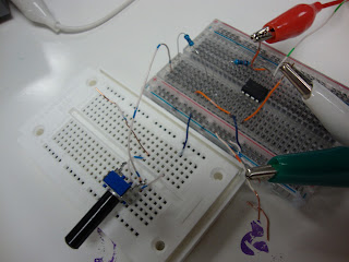
| Building the Circuit |
 |
| Finished circuit with the 12V rails |
Using the pot, we varied V_in and recorded the output.
|
V_in
(Desired)
|
V_in
(Actual)
|
V_out
(Measured)
|
V_RF
(Measured)
|
I_op
(Calculated)
|
|
0.25
V
|
0.24
V
|
-2.41
V
|
2.46
V
|
-0.0246
mA
|
|
0.5
V
|
0.50
V
|
-4.90
V
|
4.87
V
|
-0.0502
mA
|
|
1.0
V
|
1.00
V
|
-10.04
V
|
9.86
V
|
-0.1028
mA
|
I_cc = 0.874 mA
I_ee = -0.981 mA
I_cc + I_ee = -0.107 mA
P_cc = V*I = 10.488 mW
P_ee = 11.772 mW
Next we add a 1k resistor like shown below
 |
| Part 2 Circuit Diagram |
 |
| The final circuit |
However, we only took measurements when V_in = 1V.
|
V_in
(Desired)
|
V_out
(Measured)
|
V_RF
(Measured)
|
I_op
(Calculated)
|
I_cc
(Measured)
|
I_ee
(Measured)
|
|
1.0
V
|
-9.99
V
|
9.72
V
|
-0.102
mA
|
0.887
mA
|
-0.987
mA
|
I_ee + I_cc = -0.1 mA
P_cc = 10.644 mW
P_ee = 11.844 mW
Bonus:
 |
| R_f was swapped with a variable resistor |
Measured R_f = 49.9 kΩ
|
V_in
(Desired)
|
V_out
(Measured)
|
V_RF
(Measured)
|
I_op
(Calculated)
|
I_cc
(Measured)
|
I_ee
(Measured)
|
|
1.0
V
|
-5.03
V
|
4.99
V
|
-0.101
mA
|
0.885
mA
|
-0.985
mA
|
I_ee + I_cc = -0.1 mA
Conclusion:
The results are as expected because the ratio of the feedback resistors gives a gain of -10. V_in does not change the gain, only the resistors. KCL held, so the experiment was a success. To get a gain of 5, the ratio of R_i:R_f had to be 1:5, therefore R_f = 50 kΩ.

No comments:
Post a Comment